Questa è una vecchia versione del documento!
Indice
Domus Project
the project
We are working on a promising project about Building Automation.
Goals
- affordable
- flexible and interfaceable with other standards and products
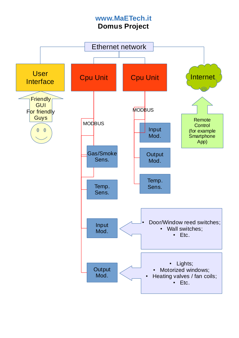
Overview
The system will be made of:
- a series of pheripherals, communicating over the well-known ModBus standard, such as:
- digital input modules;
- relay output modules;
- dimmer modules;
- anolog input modules;
- temperature sensors;
- smoke/gas sensors;
- …
- some intelligent units, that will run specific software capable of:
- communicating with the attached peripherals;
- gain autonomy (respond to inputs switching outputs etc);
- working as gateway to the Ethernet;
- be configurable in stand-alone (web interface) but when connected to a network should be ideally configurable automatically by the system (just configure the “master” device, all peripheral intelligent units will be automatically configured for stand-alone autonomy operation).
- some user interfaces (touch panels), communicating over ethernet, running specific software
- PSU
State of art
Input/output peripherals ready.
Temperature sensor still under development.
Now working on the CPU unit.
Peripherals
Generic DIN peripheral 3d view

First prototype boards:
(16 input board, 8 relay output board, temperature sensor board)


DIN - 16 dig. input module
Working prototype, featuring 16 opto-isolated inputs and modbus communication. Ready for production.

Features:
- 16 opto-isolated inputs active connecting the input to ground: easy installation;
- Input mild filtering;
- Three readable registers, one (0) for instantaneous status, one (1) for the previous status (reset after reading), one (2) for the previous status (reset after writing something to the same register).
- Input leds that indicate status of inputs, they can be enabled and disabled through pushbutton;
- Data led, indicates whenever a modbus function is accomplished;
- Error led, indicates whenever a modbus function cannot be satisfied;
- Peripheral reset button;
- 12VDC power supply.
DIN - 8 relay output module
Working prototype, no photo available, features 8 relay NO outputs. Ready for production.
Features:
- 8 relay NO outputs;
- uses OMRON G5Q relais, 250VAC 10A resistive load;
- One modbus register readable and writable;
- Front panel leds indicate status of outputs;
- Front panel leds can be enabled or disabled with a toggling pushbutton or a dip switch;
- Data led: flashes whenever modbus request has been accomplished;
- Error led: flashes whenever modbus request cannot be satisfied;
- Front panel reset button;
- 12VDC power supply.
Temperature sensor
Intelligent Units
User Interfaces
PSU
It is possible to have a PSU for each peripheral, or centralize them. Centralizing them can be convenient bacause you can use only one 12V lead acid battery as backup power for the whole system (except for additional networking infrastructures, such as ethernet switches).