Questa è una vecchia versione del documento!
Indice
Papers & notes concerning electronics
Papers
- [Datasheets directory](http://boris.maetech.it/docs/datasheets/)
- Slides [“elettronica open source - microcontrollers”](http://boris.maetech.it/docs/papers/opensourceelectronics-microcontrollers.pdf) : overview sui microcontroller, utilizzate in occasione del Linux Day 2011 a Pordenone
- Cable designations standards also pdf version
SMD Fuses Letter to Value Chart
B = 0.125
C = 0.2
D = 0.25A
E = 0.375A
F = 0.5A
X = 0.68A
G = 0.75A
H = 1.0A
J = 1.25A
K = 1.5A
L = 1.75A
N = 2.0A
O = 2.5A
P = 3.0A
R = 3.5A
S = 4.0A
T = 5.0A
(thanks to Carlo Pollice)
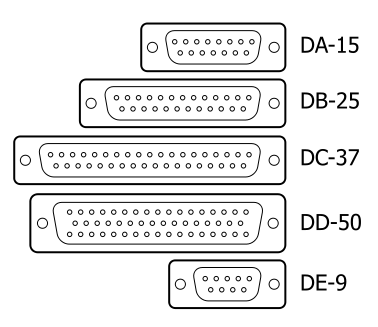
D-Sub connectors
Lamp sockets
- GY socket, one pin is bigger than the other, used for MSD discharge lamps.
- GX socket, both pins same thickness, used for PC-proj's 1000W lamps.
Pinouts & Wirings
Nellcor(r)/Sunrom pulsioximetry sensor
 numbers refer to DB9 connector pins
               IR led
 2 --------+-----|>|------+-------- 3
          |-----|<|------|
              RED led

             photodiode
 5 -------------|>|---------------- 9

 7 -------( cable main shield )

                6.0K-9.7K
 6 -------+-------/\/\/\/\---------- 1
         |
         |-------( sensor shield )
Symbol LS2106 barcode scanner ps/2 wiring / pinout
| To scanner | PS/2 | |||||
|---|---|---|---|---|---|---|
| Rj45 pin | wire colour | header pin | function | IDC pin | wire col | din pin |
| orange | 1 | data out | 2 | red | 1 (male) | |
| red | 2 | +5 Vcc | 4 | green | 4 (male) | |
| 4 | purple | 4 (female) | ||||
| yellow | 3 | ground | 3 | orange | 3 (male) | |
| 10 | orange | 3 (female) | ||||
| green | 4 | clock in | 5 | purple | 5 (male) | |
| brown | 5 | clock out | 12 | green | 5 (female) | |
| purple | 6 | data in | 14 | red | 1 (female) | |
| NC | - | - | shield | 6 | shield | shield |
Note: Male ps/2 to PC, female PS/2 to keyboard (optional)
Note: +5Vcc line interrupted by external adaptor plug: if plug is inserted, ps/2 vcc is disconnected and external + goes to scanner
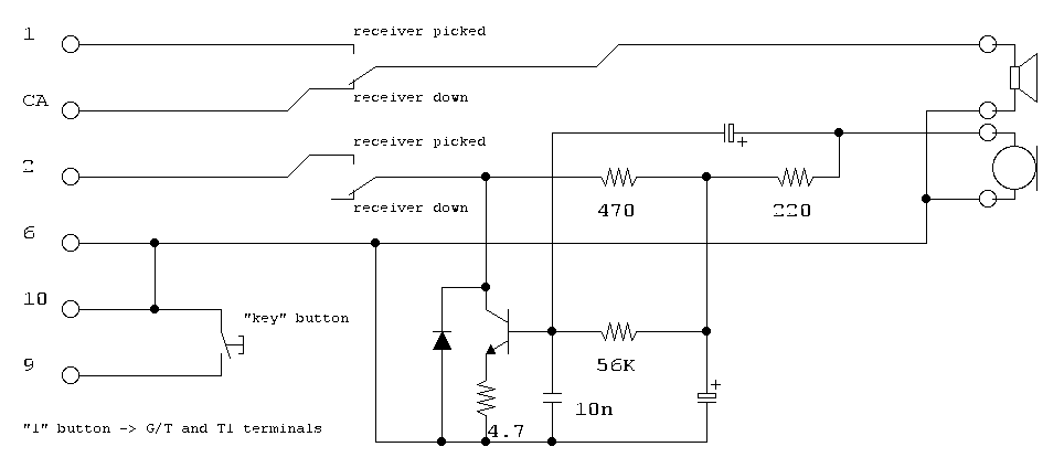
Urmet domus power supply and peripherals
External station (portiere elettrico):
- 1 don't know, maybe not amplified output
- 1A amplified microphone output
- 2 input
- -/+ audio power supply
- L should be LED
- G/T pushbuttons common
- Ux pushbuttons
Power supply module (786/15)
- PS(2) Tone generator output
- C(2)/SN(2) Current sensing circuit (to make relay trip)
- +/- Audio power supply
- -J Amplified output for intercommunicating circuit (audio is revealed from “+” !)
- Relay contacts:
- 2,5,8 common
- 1,4,7 normally open
- 3,6,9 normally closed
- C1-SN1 makes relay trip to NO, C2-SN2 makes relay relax to NC
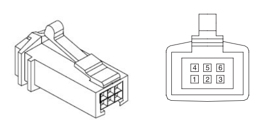
IBM 4820 Touch monitor (ELO 4500U)
Connector marked as “4” is USB device (input), optionally plus power.
P/N 14J0930, 14J0624 — FRU/SMU 42M5673, 42M5671
Referring to the image, pin 2 is D-, pin 3 is D+, pin 4&5 are GND.
A guide says pin 1 should be 5V input and pin 6 12V input, but I am not convinced about this.
AVR simple programmers
mcu      DAPA      STK200=ponyprog         DASA (serial)
VCC       3          -
RST       16         9                        7 (4.7k res. series + 5.1 zener diode to gnd)
SCK       1          6 (opt. 1k r)            4 (4.7k res. series + 5.1 zener diode to gnd)
MOSI      2          7 (opt. 1k r)            3 (4.7k res. series + 5.1 zener diode to gnd)
MISO      11         10                       8 (no add'l comp)
Cisco rj45 rs232 terminal console
RJ45 male (cisco)           DB9 female (PC)
RJ45    DB9
-       1
3       2
6       3
7       4
4+5     5
2       6
8       7
1       8
-       9

 ________
/       /|
|||||||| |
1      8
contact view
(hook is behind)
APC Smart UPS communcation rs232 cable
Dumb segnalling
UPS DB9 PC DB9
4       5
2       8
1       4
5       1
8--10k--1

Smart cable
UPS DB9 PC DB9
2       2
1       3
9       5
a version says
        1+2
        7+8
another says
        1+4
        7+8

Terminal is 2400:8n1
Sharp LCD module 1x16 alpha chars (taken from a laser printer)
pin funct
1+2 gnd
3   led buffer enable #g1
5   44780 enable
6   44780 r/w
15  vcc
16  gnd
17  44780 rs + led buffer clock
18  db4
19  db5
20  db6
21  db7
Chinese PL-2303 USB to ttl serial interface
     |^^^^^^^^^^^^^^^^^^^^^^|
^^^^^|                   o  |   <--- 3.3V out
     |  component        oo |   <--- GND
usb  |    side           oo |   <--- RX (from ext.device to the pc )
 A   |                   oo |   <--- TX (from the pc to the ext.device)
_____|                   o  |   <--- 5V out
     |______________________|
Professional 4-pin-XLR headsets
used for intercoms, etc.. 4 pin XLR : 1. MIC GND - 2. MIC SIGNAL - 3. EARPHONES GND - 4. EARPHONES SIGNAL


