How to reprogram an EOC2610's flash.
Requirements:
- an SPI/jtag interface (for example, parallel port simple jtag interface)
- SPI software (for example, spiflash, which runs on Winzozz)
- Soldering tools & skills, pieces of wire
The problem
A mistake or a power failure while trying to upload a new firmware into an EOC2610 access point, causes the device to be unusable, as it won't boot anymore. The problem is the corrupted data stored into the flash memory chip.
The solution
The only way to make it work again is to manually push the desired firmware into the flash chip. Of course you have to find a firmware (in binary data format - .bin) that can be its original one or the new one. In this case the firmware has been dumped from another one of the same access point, using
# cat /dev/mtdblock0 > file.bin
We will use a SPI/jtag interface connected to a pc to upload it to the chip. The chip likely needs to be removed from the EOC2610 board.
Hardware hack
The flash chip containing all non-volatile data is a ST M25P64 (the same of Fon 2100/2200), it communicates via serial interface and can be easily programmed with SPI method, aka JTAG interface.
An easy interface uses the LPT port on the pc. The one we used has a 74244 buffer and is shown below.
Some guides found on the internet suggested to attach the SPI directly to the chip on board. This had not worked for us, likely because the EOC2610's cpu continues feeding clock to the flash and so conflicts with our SPI.
The hack consists of removing the chip from the board. Of course removing is not simple as it is in SO package. A simple method consists in filling with soldering tin the whole lines of pins. This ensures a better heat conduction through the pins. Then gently lift the IC one one side, while keeping the soldering iron in contact, using a small screwdriver or a cutter. Then the other side. Or better a bit on one side then the other and so on.
Make sure the IC don't become too hot, alternate 1 minute of "surgery" and 30 seconds letting cool down.
Once the IC has been removed, clean up the contacts on the board and the pins on the IC. Solder some small wires to the IC pins needed (see the schematics below). The JTAG circuitry is also shown below, build your own as you prefer.
Our "dead bug" jtag prototype
In order to quickly test the solution (and restore the ap!) the interface was build using Dead Bug tecnique :)
The 74244 is powered from an external stabilized 5Vcc power supply, while the M25P64 flash chip is powered at 3,3V from the EOC2610 board itself.
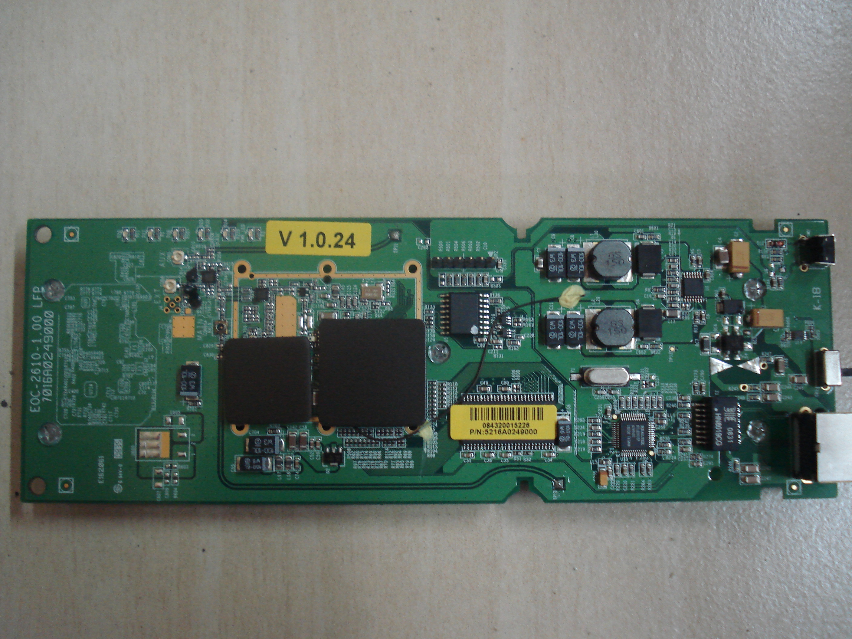
Looking at the EOC2610 board you can see a pin strip connector, pin 1 is 3,3Vcc power, pin 2 is Ground.
Using these supplies there is no need of resistors between the LPT cable and the 74244. There must be resistors (100-220 ohm) between 74244 and the flash chip.
Alternatively also the 74244 could be powered at 3,3V. This way the resistors should go between 74244 and LPT interface.
Datasheets are attached at the end of the article, pls note Write Protect and Hold pins of the flash chip should be pulled high (3v3).

Flashing
Install and run SPIFlash. Connect the interface and check by clicking "check ID". Should return the chip information, if returns unknown please double check the interface, the chip connections and/or reboot windozz.
Erase the chip to be sure. Load the firmware file. Press "program" button.
Press "verify" button if you want, if it is OK you can now solder the chip back to the board.
We prefered to connect the chip to the board through wires for the first check, to be sure we should not have to unsolder the chip again.
Finish ;-)
IMPORTANT: The uploaded (new) firmware contains the mac address which is obviously not the one printed on the eoc-2610's label.
It seems sufficient to run this command in telnet to change the MAC once for all.
/etc/write_mac.sh [LAN MAC] [WIRELESS MAC]
FYI: MTD (flash memory) structure
# cat /proc/mtd

	dev: size erasesize name

	mtd0: 00800000 00010000 "spiflash"

	mtd1: 00030000 00010000 "RedBoot"

	mtd2: 003f0000 00010000 "rootfs"

	mtd3: 000a0000 00010000 "vmlinux.bin.l7"

	mtd4: 00020000 00010000 "cfg"

	mtd5: 00300000 00010000 "unallocated space"

	mtd6: 0000f000 00010000 "FIS directory"

	mtd7: 00001000 00010000 "RedBoot config"
Resources
- google && forums
-
JATG Schematics
http://spiflash.org/schematics.zip
Alternatively, you can use tjtag and the wiggler jtag interface. -
Programming software
http://spiflash.org/spiflash.zip -
Firmware
original_eoc2610.bin -
Datasheet
25p64
74244