Questa è una vecchia versione del documento!
Quiz Show System
The system is made of 3 quiz stations with big red pushbutton and lights, and a controller.
The competitor reserves to answer the question by pushing the button, his lights turn on and a sound is emitted. Then the other stations are disabled, until the presenter resets the system.
The system has been projected with totally electro mechanical circuits, no digital ICs. So it is simple concept, reliable, and can be expanded with digital controls in a future.


User manual available (italian language only) http://boris.maetech.it/docs/proj/quiz/usermanual_it.pdf
Project and Schematics
The project has been published at Instructables
To obtain the behavior descripted above you may want to proceed in two different ways:
- microcontroller or digital circuitry : one or more chips on electronic board are enough to make the logical part of the “quiz system”. PRO: fully customizable, cheap (especially for on-scale production), centralized. CONTRO: more design time is needed, realization of one prototype needs time.
- electromechanical circuitry : the logic is reached through diodes and relays. PRO: cheap, easy to build, reliable. CONTRO: not for on-scale production, not customizable, complexity grows up with number of stations.
The second way was initially only a challenge, but then I've started to figure it out as the best choice. The interesting thing is that the electromechanical circuit is a skeleton onto which you can build, in a future, an eventual digital/computerized management.
So here's the full circuit (click on the picture to see it larger).
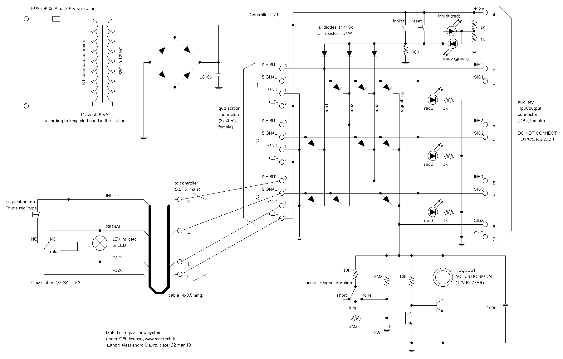
The relays are decentralized as they are part of the pushbutton/lamp system circuit. In this way it is more logical and easy to build. The buttons are Normally Closed, so they keep the relay excited closing its circuit. When the button is pressed the relay is released so two things happen: the button-relay circuit is opened, so if the button is released nothing happens (this ensures precise survey of the push instant), and the other circuit is closed turning on the luminous indicator, the acoustic indicator, and forcing the others relays on. The last matter is achieved through a network of diodes. Of course, the more stations you want, the more complicated is the network. Last but not least, reset and inhibit switches (logically different, electrically the same) will force all the relays on, closing again their circuits until a big red button is pressed.
The part of the circuit where a microcontroller is most missing, is acoustic signal. It has to be limited in time so some kind of timer is needed. A microcontroller would have done this by software with no problems (…fully customizable… meant this). The network on the bottom of schematics provide a good enough timer (not precise, because the Cap have to discharge between one reservation and the other), with the possibility of choice between short, long and none.
Realization
Take a look at the pictures to see how it has been realized.
The project has been published at Instructables.


Expansion
Recently, the system was used in a theater, and improved with automatic audio/video/light response.
An Arduino (for shortest development time) was used to read the quiz controller's outputs provided on the “expansion connector”, and to generate MIDI commands to raise lighting console's memories. An additional DMX Switcher provided go/stop signals for the audio sound and switched video between 4 cameras (one for each competitor, one for general purpose / presenter).
The whole system was very astonishing.