Questa è una vecchia versione del documento!
Indice
Immergas Zeus 24 Maior schematics and repairing
Schematics - Reference
From the user manual
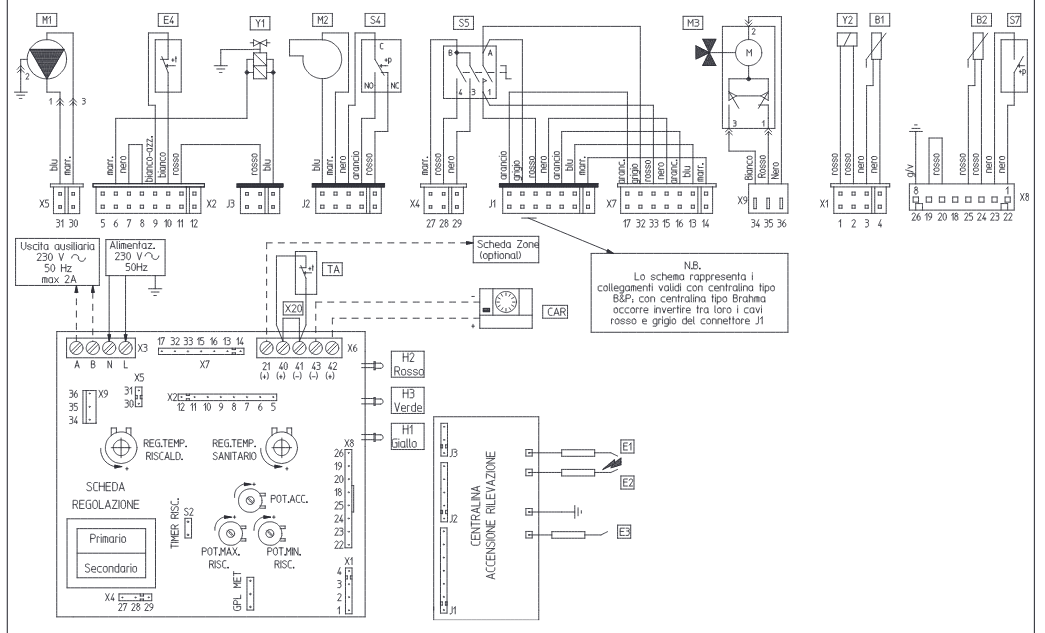
LEGENDA:
- B1 - Sonda NTC mandata
- B2 - Sonda NTC sanitario
- CAR - Comando amico remoto (optional)
- E1-E2 - Candelette accensione
- E3 - Candeletta rilevazione
- E4 - Termostato di sicurezza
- H1 - Led alimentazione valvola gas
- H2 - Led segnalazione blocco
- H3 - Led presenza rete
- M1 - Circolatore
- M2 - Ventilatore fumi
- M3 - Motorino tre vie
- S4 - Micro pressostato fumi
- S5 - Interruttore generale
- S7 - Micro pressostato impianto
- TA - Termostato ambiente On/Off (optional)
- X20 - Ponte inibizione TA o CAR
- Y1 - Valvola gas
- Y2 - Modulatore valvola gas
Details of MAIN REGULATION BOARD
X2 has the following links : 11-10 , 9-8, 7-6 . Between the links are optocouplers that feel the power to the GAS VALVE and/or the overheat.
X7, 17 and 16 are switched together through a relays contact. This gives the consent to the Burner Board.
Details of BURNER CONTROL BOARD
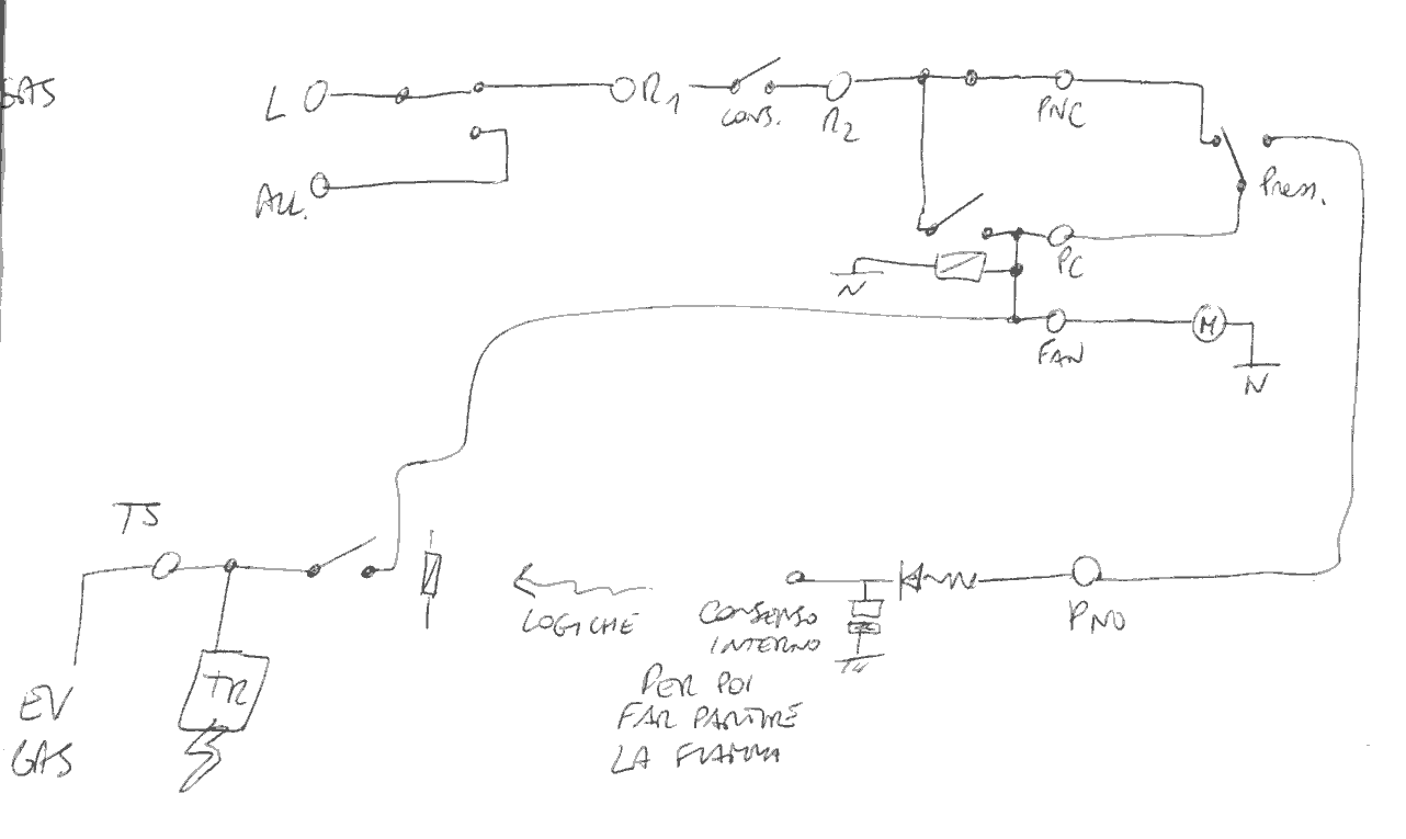
The whole ignition path schematic
This schematic is a view of the whole circuit that controls ignition. It comprehends parts of the two boards and other components and adopts some semplifications.
The repairing
The common problems concerns relays and capacitors on the Burner Board.
The cap. after R33, parallel to coil of “central” relais, was dried in my case, thus relay oscillated at 50Hz and damaged its contacts. Replacing the cap. (10uF/63V) and the relais (OMRON 48V), had the furnace back alive.


